
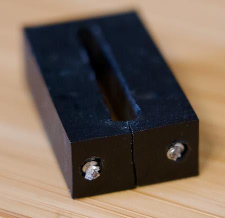
// Finished Prototype
FormLabs Tough 2000 Resin prototype — Long-EZ
nose gear retraction system · 2024
Long-EZ Experimental Aircraft — Nose Gear Retraction System
Analyzed and resolved a critical landing gear malfunction on a Long-EZ experimental aircraft by diagnosing issues within the nose gear retraction system. The original bracket had sheared off due to incorrect positioning caused by malfunctioning limit switches — a damaged microswitch resulted in incorrect position indications, causing the actuator to over-travel. When the override was activated without accurate feedback, excessive force was applied to the bracket, ultimately shearing it off.
A replacement bracket was redesigned in SolidWorks and prototyped in FormLabs Tough 2000 Resin. The new design positions the sled close to the limit switches, ensuring the ramps on the top and bottom make contact to activate the up and down switches accurately — stopping rollers from falling into adjustment slots and restoring reliable nose gear position feedback.
The prototype was not ultimately implemented. During the process, it was determined that the limit switch the bracket was designed for was extremely cheap and prone to failure. Rather than continuing with a redesigned bracket around an unreliable component, the decision was made to invest in a full replacement of the original system — a more robust long-term solution.
// Key Specifications
// NOTE — This prototype was not implemented.
Full system replacement was ultimately selected
over redesigning around an unreliable component.
01 — Root Cause
A damaged microswitch provided incorrect position indications to the nose gear retraction system, causing the actuator to over-travel beyond its intended range of motion.
02 — Failure Mode
When the override was activated without accurate limit switch feedback, excessive force was applied to the bracket. The bracket sheared off due to the combined effect of incorrect positioning and actuator over-travel.
03 — Parts Scarcity
The original limit switch components were obsolete and no longer available. The redesign adapted widely available microswitches as direct replacements, addressing both the mechanical failure and the parts scarcity problem.
Original Bracket — Shear Failure
The original bracket sheared off due to incorrect positioning caused by malfunctioning limit switches. Actuator over-travel under override conditions applied excessive force to the bracket.

Nose Retraction System
This bracket positions the sled (aluminum bar) close to the limit switches, ensuring the ramps on the top and bottom make contact to activate the up and down switches accurately.
Redesigned Bracket — Prototype
The new bracket design stops rollers from falling into adjustment slots and ensures accurate gear position feedback. Easy to install and more durable than the original.
Performed hands-on inspection of the Long-EZ nose gear retraction system to identify the root cause of the landing gear malfunction. Traced the failure to a damaged microswitch providing incorrect position indications, causing actuator over-travel.
Removed and documented the sheared bracket. Measured and recorded all critical dimensions, interface geometry, and mounting features to establish a baseline for the redesign.
Reverse engineered the original bracket geometry from the failed part and surrounding system components to fully understand the design intent and identify improvements.
Redesigned the bracket in SolidWorks with improved geometry to prevent roller fallout into adjustment slots and ensure accurate up/down switch activation. Adapted design to accommodate widely available replacement microswitches.
Printed prototype in FormLabs Tough 2000 Resin — selected for its impact resistance and dimensional accuracy, appropriate for functional aerospace prototype validation.
Test fitted prototype in the nose gear retraction system. Verified sled positioning, ramp contact geometry, and switch activation timing. Iterated on geometry based on fitment findings.
During the validation process, it was determined that the limit switch the bracket was designed for was extremely cheap and prone to premature failure. Continuing to design around an unreliable component was not an acceptable long-term solution. The decision was made to invest in a full replacement of the original system.
Engineering Analysis
CAD & Design
Fabrication & Process