// Prototype Test Fit
Wood prototype test fit — preparing for
polished aluminum production · 2026
Light Diffusion Through Ribbed Airfoil Geometry — Preparing for Polished Aluminum Production
A lamp designed to diffuse light through a ribbed airfoil geometry — the internal profile of an airfoil cross-section reflects and distributes light through the structural ribbing, creating a layered, dynamic lighting effect.
Currently in the final design stage with a wood prototype used to validate geometry, rib spacing, and light diffusion behavior. Part files are being prepared for production in 1/8" polished aluminum, to be laser cut on a Boss Laser HP3655 155W engraver.
The transition from wood to polished aluminum will dramatically change the light behavior — from warm diffusion to sharp internal reflections characteristic of a polished metal interior.
// Key Specifications
Lamp Assembly — SolidWorks Model
Developed the lamp concept around the internal geometry of an airfoil cross-section. The ribbing structure that defines an airfoil's shape was adapted to serve as both the structural and aesthetic element of the lamp — diffusing and reflecting light through each rib.
Modeled the full lamp assembly in SolidWorks — including the airfoil profile, rib spacing, base, and internal light housing. Geometry optimized for laser cutting in sheet material.
Laser cut wood prototype on the Boss Laser HP3655 155W to validate geometry, rib spacing, assembly fit, and light diffusion behavior before committing to aluminum production.
Incorporating lessons from the wood prototype into the final SolidWorks part files. Preparing production- ready files for laser cutting in 1/8" polished aluminum. The polished aluminum interior will create sharp internal reflections — a significant upgrade from the warm diffusion of the wood prototype.
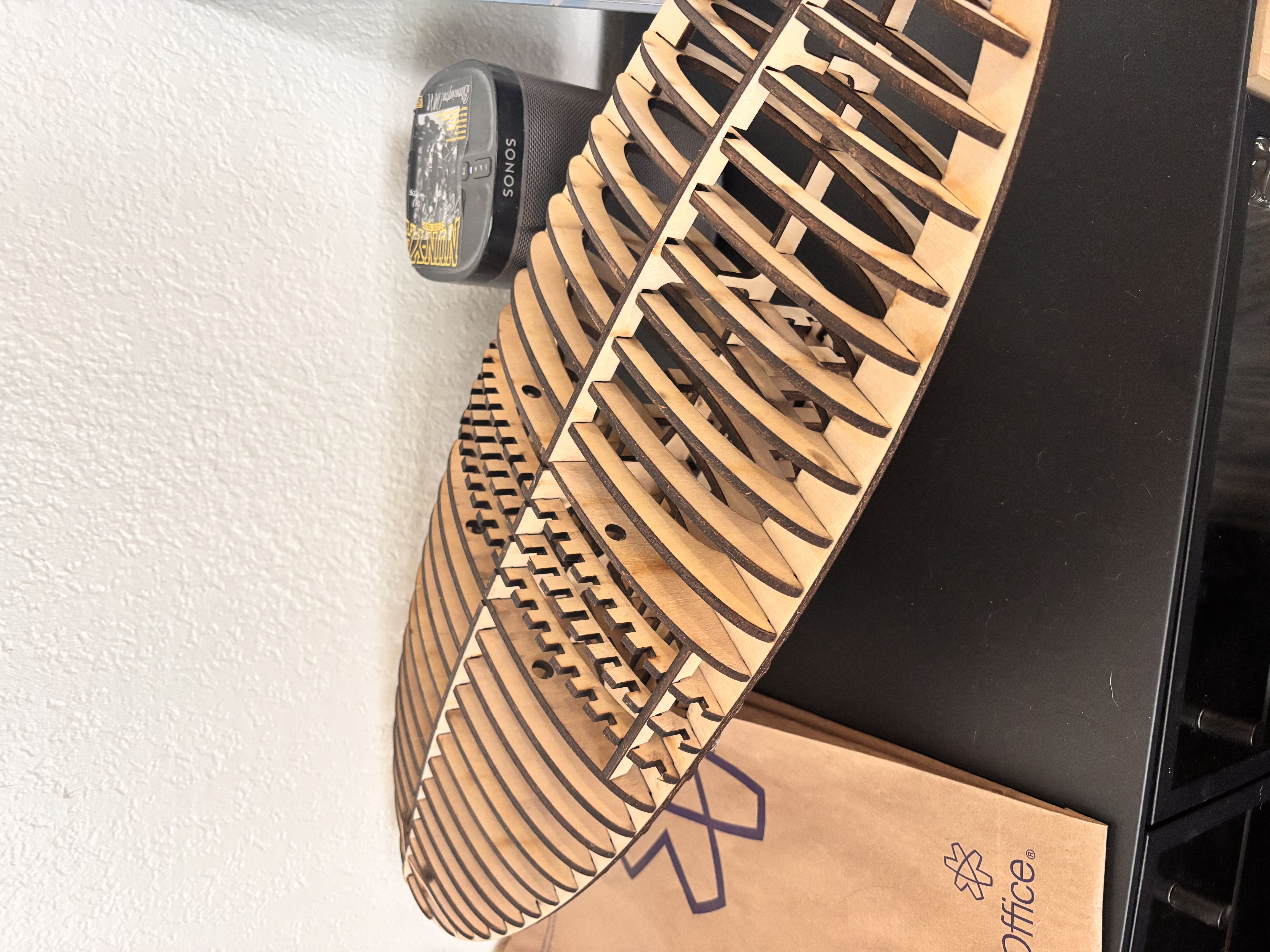
Prototype Test Fit
Wood prototype assembled and test fitted to validate geometry, rib spacing, and light diffusion behavior.
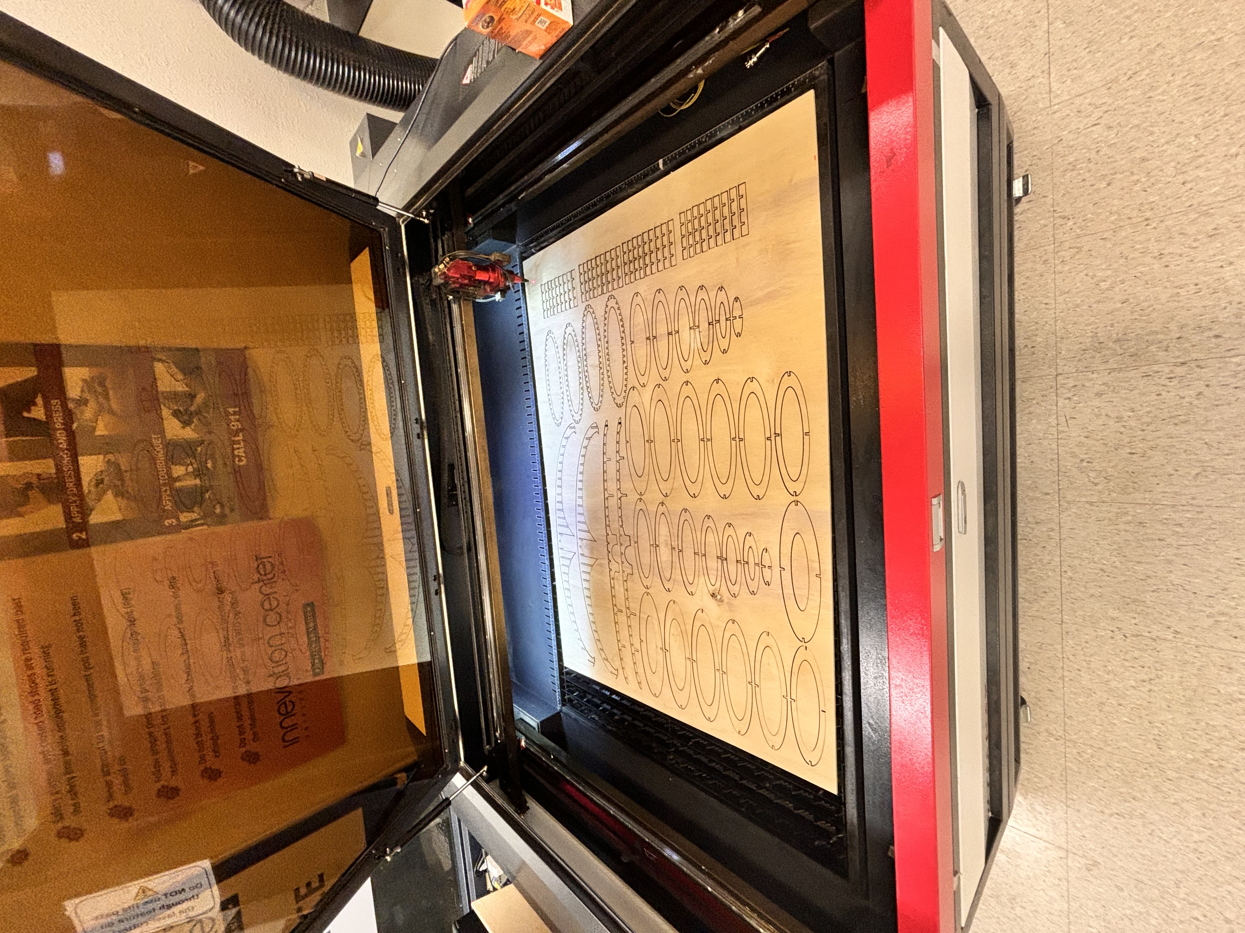
Laser Cutting
Parts being cut on the Boss Laser HP3655 155W laser cutter/engraver.
Design
Fabrication
Process